Treatments
This subdirectory contains simulations that illustrate how to simulate various experimental treatments, which are applied to neurons and neural network.
The *.trt files in SNNAP can simulate four type of treatment: i) current injection (keyword CURNT_INJ:), ii) application of a modulatory transmitter (keyword MOD_INJ:), iii) voltage clamp (keyword VCLAMP:) and iv) current clamp (keyword ICLAMP:). In addition to applying simple step functions, SNNAP can inject current with complex waveforms, such as sine waves, exponential functions, and sawtooth rectangular patterns. These more complex functions are specified both the in *.trt file and the *.fnc files.
In addition to these four treatments, SNNAP can simulate the introduction of noise (i.e., stochastic fluctuations) into any type of conductance within a model (i.e., the ‘g’ parameters in the *.vdg, *.cs and *.es files). The process of applying noise to a simulation is control by the *.R files.
Finally, SNNAP can operate in a Batch Mode in which simulations are automatically rerun while values for user specified parameters are systematically varied. The batch mode of operation is specified in the *.bch file.
Batch TEST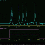
The goal of the present simulations was to illustrate how to use the batch mode of operation in SNNAP.
The batch model of operation allows the user to automatically run multiple simulations while varying the values of selected parameters. The results of these simulations can be displayed on the screen, printed, or stored to files.
The batch mode of operation can manipulate parameters that are located in the treatment files (e.g., the magnitude or duration of a current injection or voltage-clamp step etc.), in the neuron files (e.g., the membrane capacitance of a cell), or in a fmu-type file (e.g., a *.vdg, *.A, *.h, etc.). The batch mode of operation can not currently modify parameters in the *.cell or *.ws files. When run in the batch mode, the user has the option of superimposing the traces, clearing the screen between each simulation, printing each simulation or saving the results to a file.
The results of these simulation are illustrated in trtTstBch.gif, neu_test_bch.gif and fmuTstBch.gif.
fnc test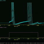
The goal of the present simulations is to illustrate how the function_treatment operates in SNNAP.
The general aspects of the *.fnc file are described in ‘treatment_function.txt’. Briefly, this feature of SNNAP allows the user to apply complex waveforms to some of the treatments described in the *.trt file. At present, the *.fnc feature only works with the current injection (i.e., keyword CURNT_INJ: in the *.trt file).
Five simulations are included in this example:
Note: Each of these treatments can be made more complicated by have multiple waveforms interacting (see treatment_function.txt).
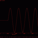 fnc_1_ous smu_1.smu illustrates the sine wave treatment
(see fnc1ous.gif).
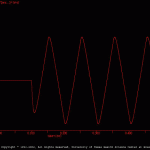 fnc2ous smu_2.smu illustrates the sawtooth (i.e., triangle waveform)
treatment (see fnc2ous.gif).
 fnc3ous smu_3.smu illustrate the linear ramp treatment
(see fnc3ous.gif).
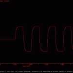 fnc4ous smu_4.smu illustrates the square wave treatment
(see fnc4ous.gif).
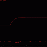 fnc5ous smu_5.smu illustrate an exponential treatment
(see fnc5ous.gif).
iclamp test
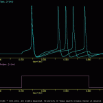
The goal of the present simulation is to illustrate the function the ‘iclamp’ function in the treatment file (i.e., *.trt).
In the voltage-clamp procedure, the membrane potential of a cell is ‘clamped’ (i.e., held) at a fixed potential, which is designed by the experimentalist. SNNAP offers a novel treatment, which is similar to the voltage clamp. This novel treatment is the ‘current clamp’ (i.e., iclamp). This ‘current clamp’ is not be confused with the experimental procedure of injecting a constant level of current, which in SNNAP is the current injection treatment (i.e., keyword CURNT_INJ: in the *.trt file). The SNNAP version of ‘current clamp’ allows the user to clamp a specified membrane current to a designated level. Thus, the user may use this treatment to evaluate the role that a give membrane current may play in the properties of a neuron.
In the present simulation, a ‘generic’ neuron model was used. This model contained a sodium, potassium and leakage current. The resting membrane of the model is -60 mV. The treatment file applies an ‘iclamp’ treatment to the sodium current (i.e., Ivd[Na.a…]<{ivr} and IVDxREG[Na.a…]<{ivr}). The ‘iclamp’ procedure clamps the inward sodium current from 0 to -2, and as a result of this inward current the membrane potential (i.e., V[a….]<{svr}) is depolarized.
The results of the present simulation are illustrated in iclamp_test.gif.
R cs test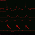
The goal of the present simulation is to illustrate how to introduce noise (i.e., random fluctuations) into a synaptic conductance.
This example simulates a simple two cell network (cells A and B) and one chemical synaptic connection from cell a to cell b (i.e., (a_2_b.cs). The *.cs file specifies several parameters such as the maximum synaptic conductance (i.e., g) and the reversal potential (i.e., E) and several files such as the time-dependent activation function (i.e., *.fAt) and the ‘noise’ function (i.e, *.R).
R vdg test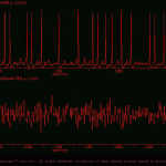
The goal of the present simulation is to illustrate how the user can introduce random fluctuations into membrane conductances.
Version 7 of SNNAP allows the user to introduce random fluctuations into any or all conductances (i.e., membrane conductances, synaptic conductances and coupling conductances). These random fluctuations (i.e., noise) are specified in *.R files. The present simulation illustrates how to introduce noise into a membrane conductance.
Voltage Clamp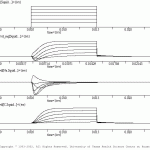
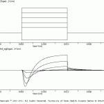
These example illustrates how to simulate a voltage-clamp experiment. The neuronal model is the Hodgkin-Huxley model of the squid giant axon. Two simulations are included: 1) V_C_total_Im.smu, which illustrates the total membrane current (Im) elicited during voltage-clamp steps; 2) V_C_Ina_Ik.smu, which illustrates the individual Na (Ina) and K (Ik) currents.
The first treatment is the holding potential and it lasts the entire duration of the simulation. The second is step potential, which lasts for a shorter time. The user may also use the *.fnc option (see the \examples\treatments\fnc_test subdirectory and manual for more details.
The results of these two simulations (in batch mode) are illustrated in vclmp.gif and VCTtlIm.gif.